
How to Build a Custom Driveline for an Overland Truck | Driveshaft Design Explained
When building an expedition truck like Rufus, one of the most critical components for transferring power from the transmission to the wheels is the driveline. However, achieving optimal performance and reliability requires careful attention to detail in the design and selection of components. In this post, we’ll walk through the driveline configuration we built for Rufus, focusing on U-joint and driveshaft design, and how we addressed common challenges with a mix of technical precision and practical solutions.
The Importance of Driveline Design
A well-designed driveline is essential for the smooth operation of any four-wheel-drive vehicle. It is made up of several critical components, including driveshafts, U-joints, and slip joints. The purpose of these parts is to ensure power is efficiently transferred from the transmission to the axles while allowing for suspension movement and frame articulation.
For our expedition truck, we wanted a robust, single-piece design that would be both serviceable and reliable in the field. Here’s how we approached the task.
Driveshaft Configuration: The Three-Piece Solution
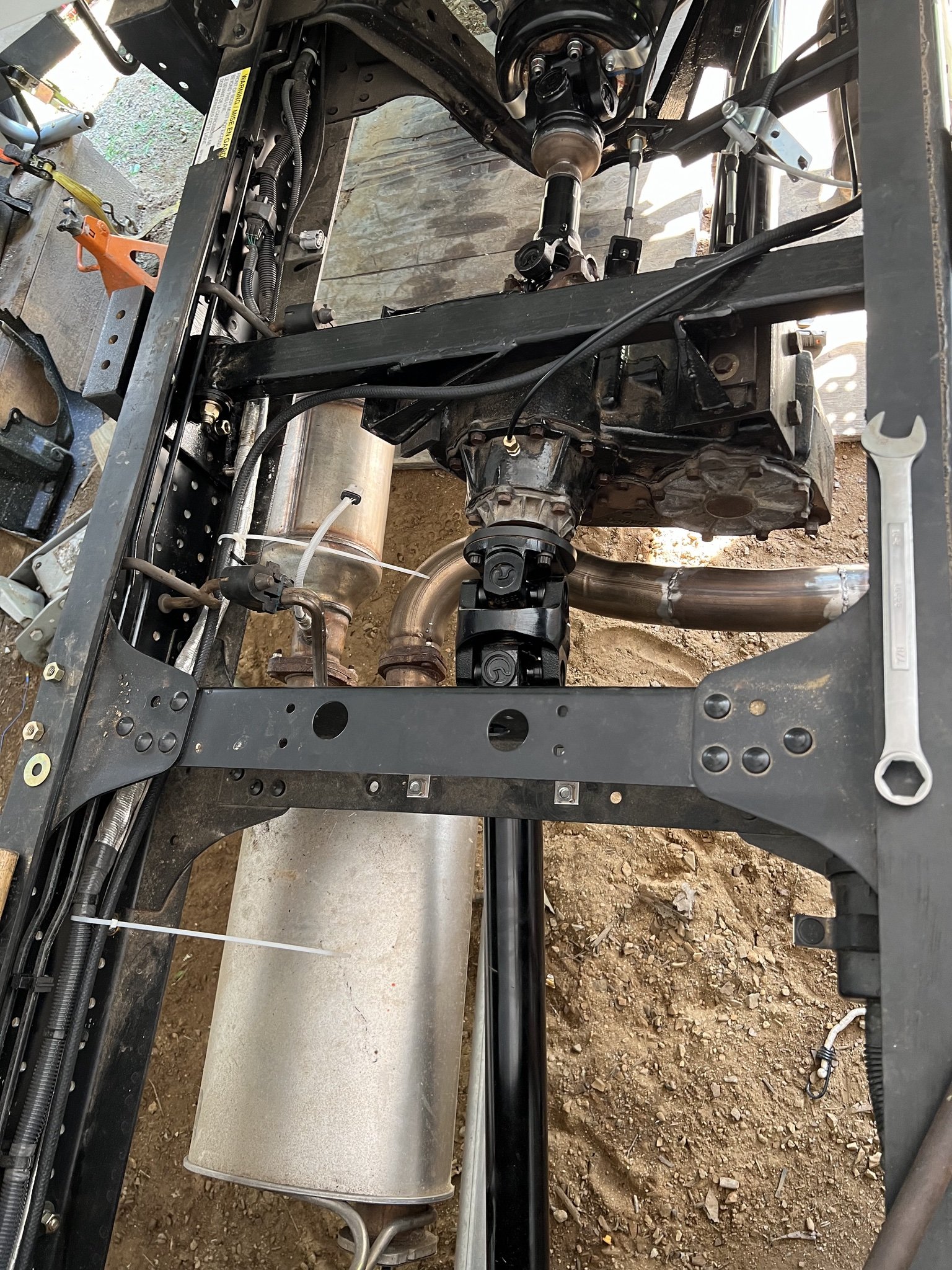
To get power from the transmission to the wheels, Rufus required three distinct driveshafts: an intermediate shaft between the transmission and transfer case, and two longer shafts for the front and rear axles. The challenge? To create simple, strong, and maintainable shafts using widely available parts while adhering to technical specifications for U-joint angles and driveline geometry.
Key Components of the Driveline:
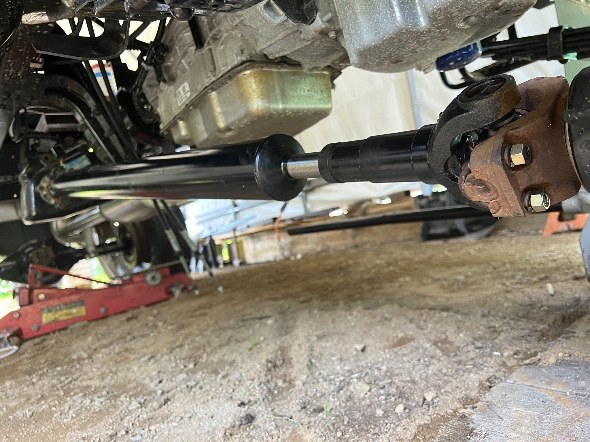
U-Joints: At both ends of the driveshaft, we used U-joints to connect components and allow for misalignment and movement. These joints are crucial for maintaining power transfer while compensating for changes in angle.
Slip Joint: A slip joint between the U-joints allows for length changes during suspension travel, which is essential for maintaining driveshaft integrity over time.
While the concept behind driveshafts is relatively straightforward, precision is paramount. The complexity lies in how these components are integrated to ensure the system operates smoothly without introducing vibrations or undue wear.
Custom Design for Rufus: Challenges and Solutions
Rufus’ driveline posed unique challenges. The output from the transmission connects via a flange to the emergency brake housing with an Isuzu-specific 4 bolt flange connection. This setup uses a 1480 U-joint, which presents potential sourcing issues if replacement is needed—an unfortunate reality, but a manageable risk with a spare in the toolbox.
U-Joint Angles and Vibration Mitigation
One of the most critical aspects of driveline design is ensuring that U-joint angles are optimized to avoid vibrations. If the U-joint angles are not equal and opposite, it can lead to undesirable harmonic vibrations that affect vehicle performance.
Angle Considerations: U-joints must maintain at least a 1-2° angle to facilitate proper lubrication, but in most instances no more than 7°. Uneven angles can cause uneven rotational speeds, leading to vibrations.
Balancing Angles: For Rufus, the goal was to maintain equal U-joint angles across each shaft, which required adjusting the transfer case angle relative to the transmission. We settled on a solution that required the transfer case to be raised by 0.375 inches to achieve this. More on this in our transfer case post.
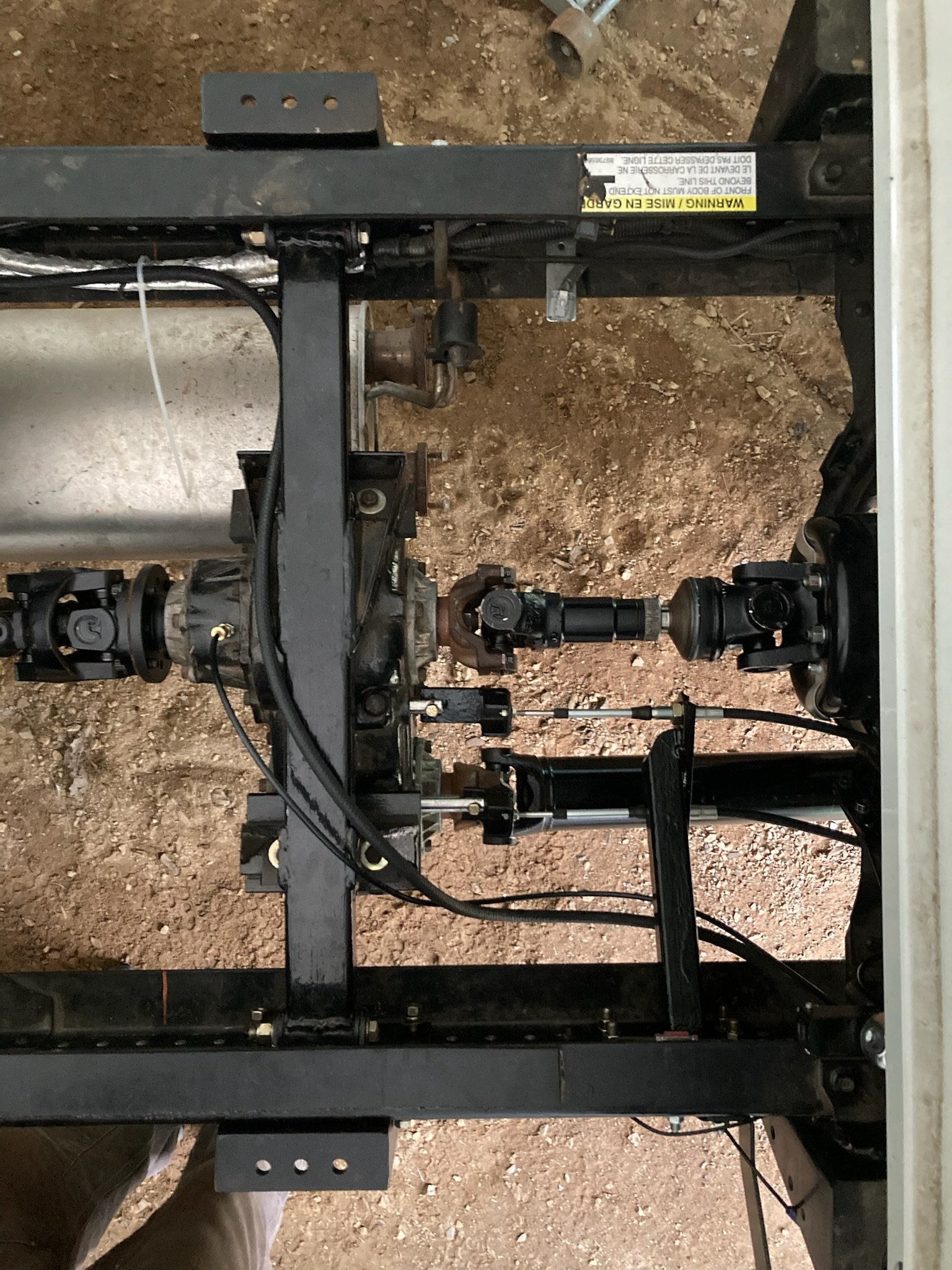
The Final Driveline Design
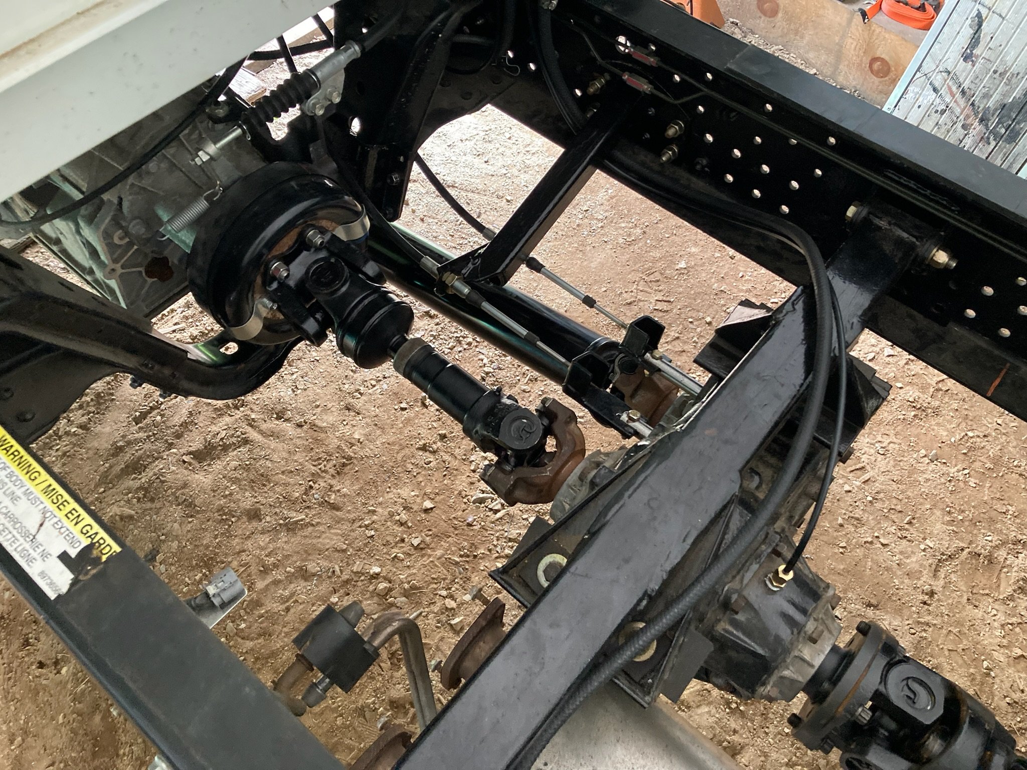
Intermediate Shaft:
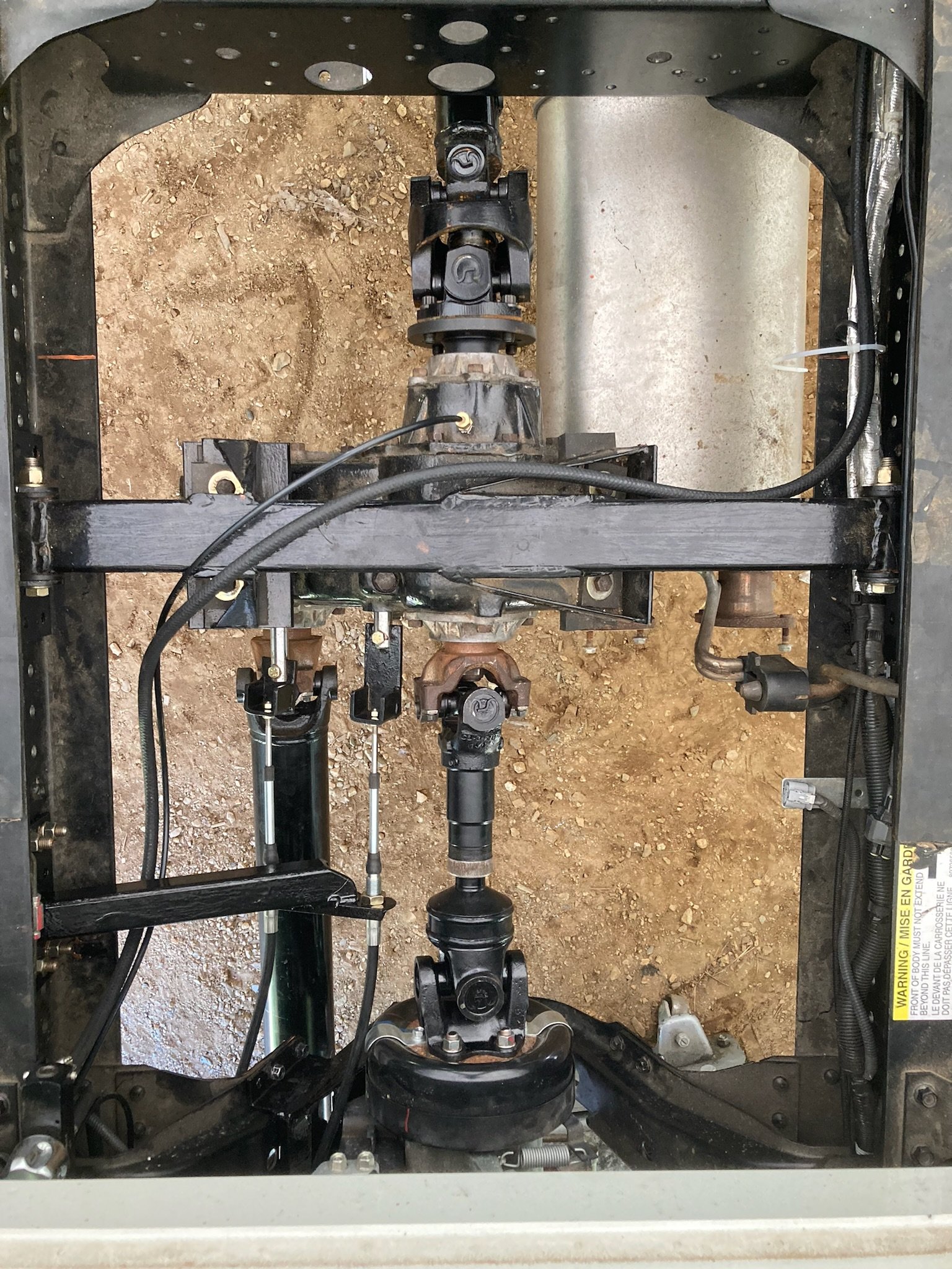
Length: 15.25 inches – a short but essential piece.
U-Joint Sizes: A 1480 U-joint at the front and a 1410 U-joint at the transfer case. While not ideal, the reduced U-joint size was a necessary compromise due to space constraints.
Slip Joint: The shortest slip joint available, ensuring smooth movement without compromising strength.
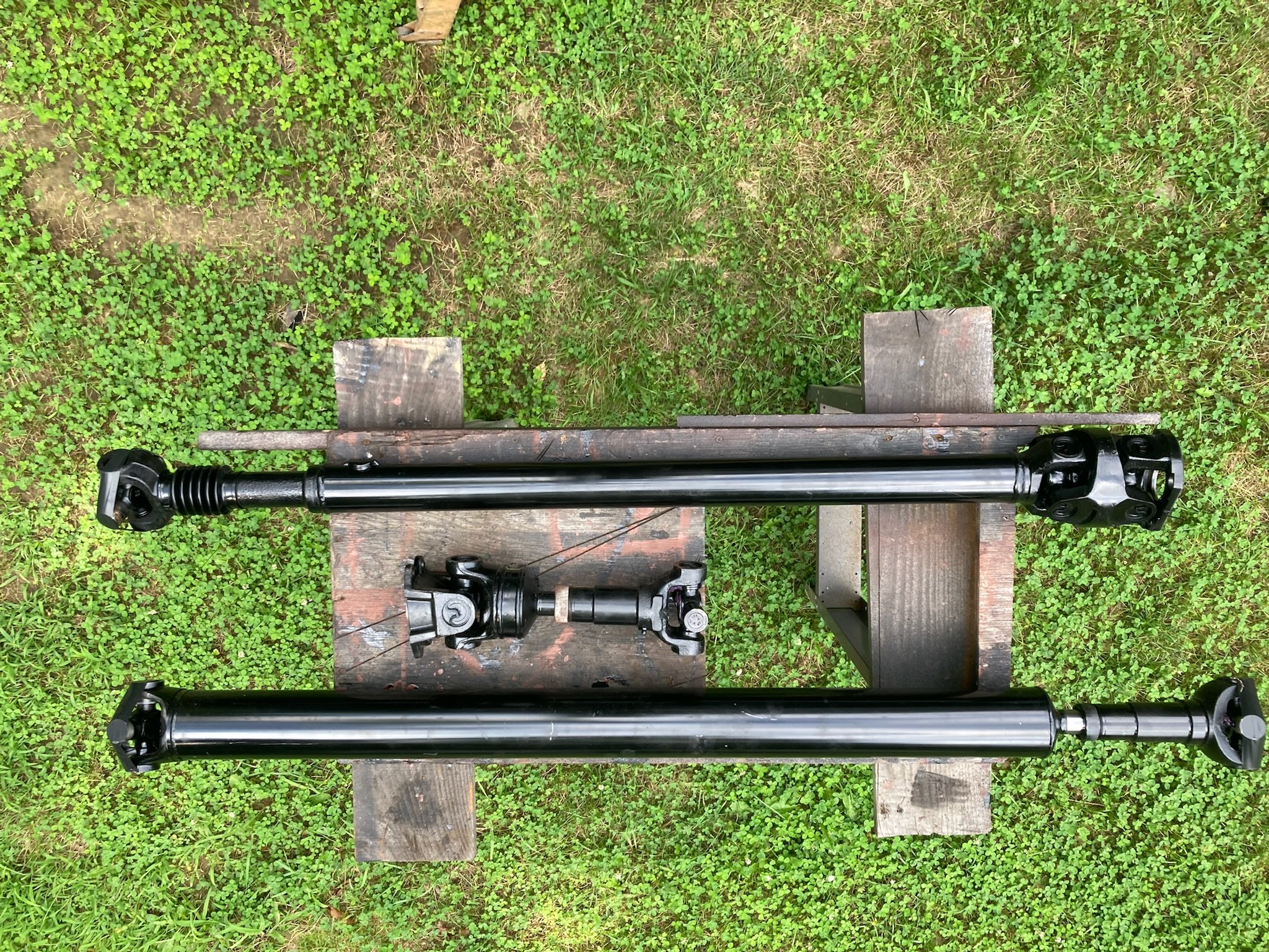
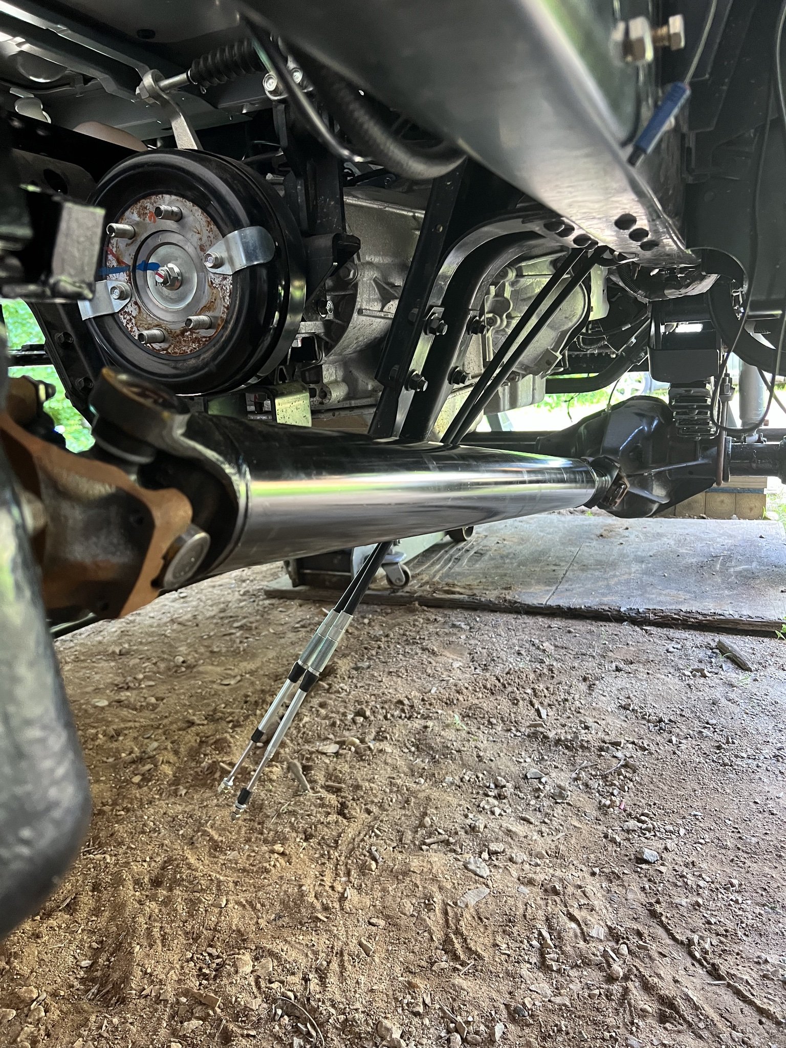
Rear Shaft:
Length: 50 inches.
U-Joint Configuration: A 1410 double cardan joint at the transfer case flange, paired with a single cardan 1410 U-joint at the pinion yoke. The rear shaft required the pinion to be rotated 2° above the driveshaft angle to compensate for spring wrap, ensuring smooth operation.
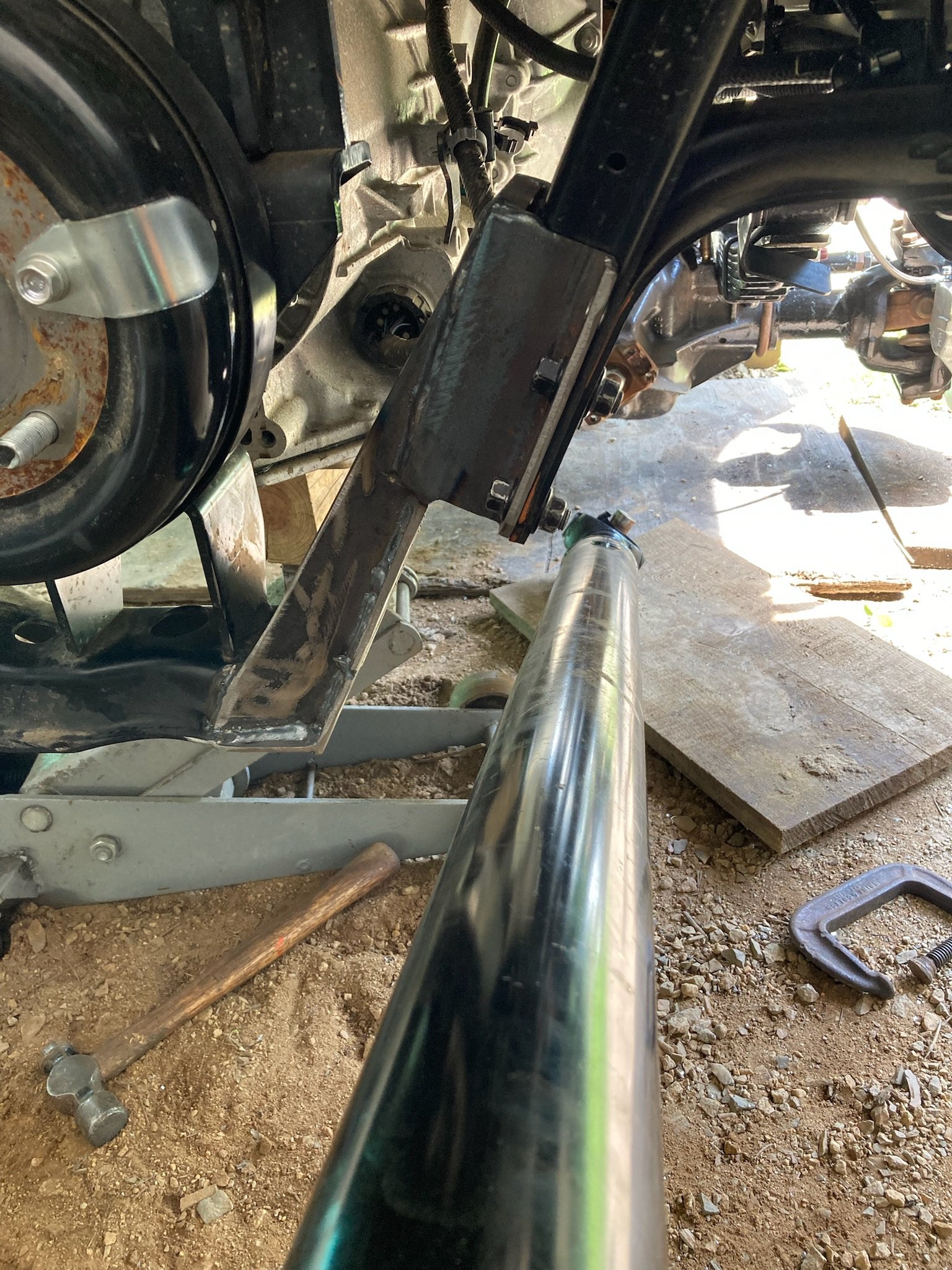
Front Shaft:
Length: 52 inches.
U-Joint Configuration: A single cardan 1410 U-joint at each end, with a slip joint in between. A yoke on the transfer case and yoke on the Dana 60 front axle.
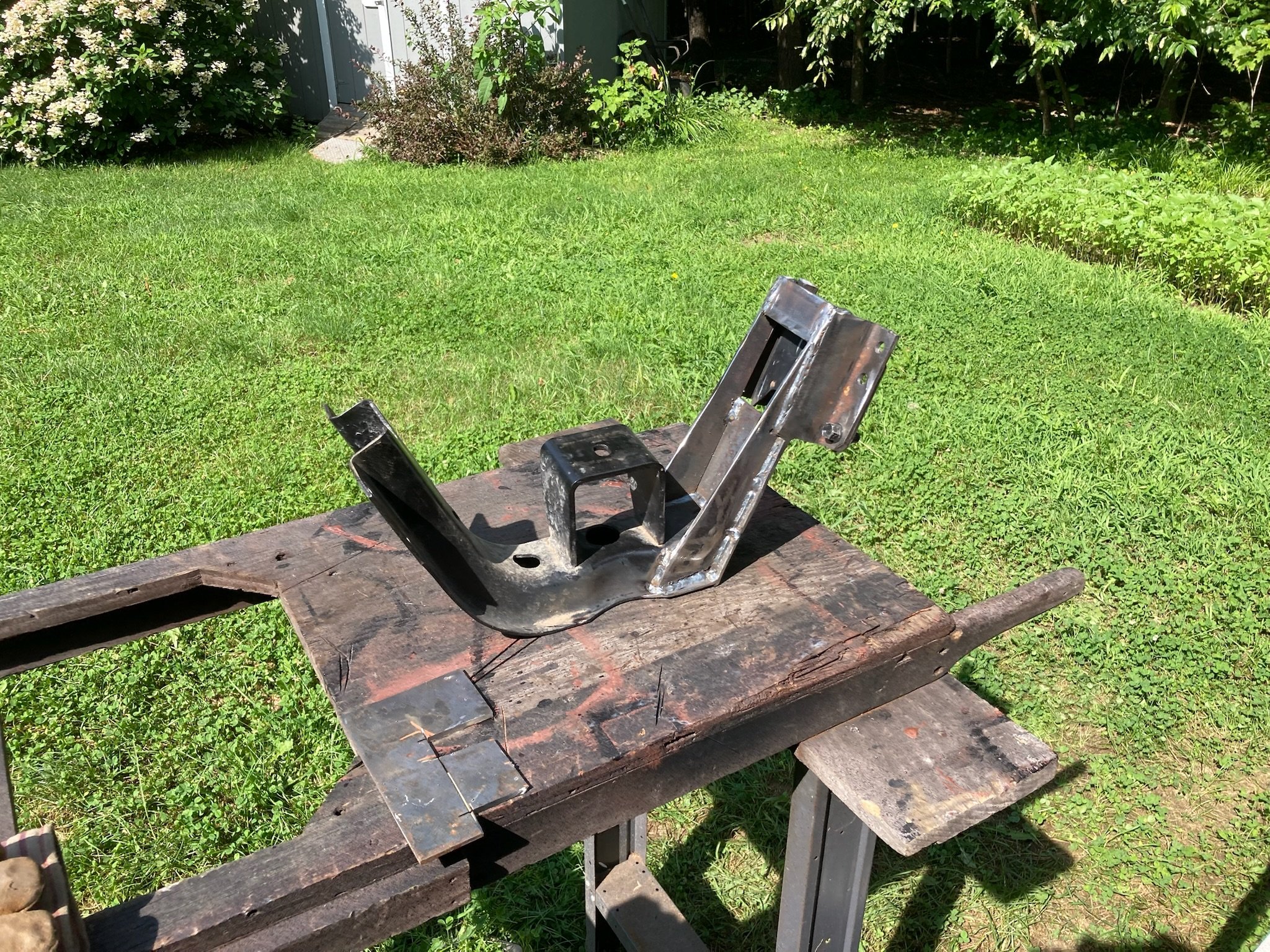
Design considerations: Although the factory transmission mount initially obstructed the use of a straight shaft, we opted to modify the mount instead of going with a two-piece shaft. We did this for simplicity and reliability.
Final Considerations and Results
After 13,000 miles, the driveline configuration has proven reliable, with no major vibrations or operational issues. All but one U-joint uses the 1410 size, and we carry spares for both sizes to ensure quick fixes in the back country. While the front shaft’s angles aren’t perfect, the system works well given the minimal demands of the front drivetrain.
In hindsight, we might have considered a married transfer case for a more integrated solution, but this setup has been robust and effective. The system is built to last, serviceable with common parts, and optimized for the challenging environments Rufus will face on its adventures.
Designing and building a custom driveline is no simple task, but with careful attention to U-joint angles, flange alignments, and suspension geometry, it's possible to create a robust and reliable system. Rufus’ driveline configuration is a testament to the importance of understanding the technical nuances and making smart, adaptable decisions. The final result is a smooth-running, dependable system that will stand up to the toughest challenges on and off the road.